A demultiplexer, often abbreviated as a demux, is a crucial device in the field of telecommunications and electronics. It takes a single input signal and distributes it to one of several output lines based on the control signals. This ability makes it highly versatile, and it can be configured for a wide range of applications. As a demultiplexer supplier, I'll guide you through the process of configuring a demultiplexer for different applications.
Understanding the Basics of a Demultiplexer
Before diving into the configuration, it's essential to understand the basic structure of a demultiplexer. A demultiplexer typically has one data input line, multiple output lines, and a set of control lines. The number of output lines is determined by the number of control lines. For example, a 1-to-4 demultiplexer has 2 control lines (since 2^2 = 4), a 1-to-8 demultiplexer has 3 control lines (2^3 = 8), and so on.
The control lines act as an address to select which output line the input signal will be routed to. When the control lines are set to a specific binary value, the corresponding output line is activated, and the input signal appears at that output.
Configuring a Demultiplexer for Signal Routing
One of the most common applications of a demultiplexer is signal routing. In a complex communication system, there may be a need to direct a single input signal to different destinations based on certain conditions.

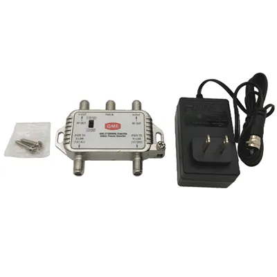
Let's say you have a satellite communication system where you receive a single satellite signal and need to distribute it to different receivers. You can use a demultiplexer to achieve this. For instance, if you have 4 receivers, you can use a 1-to-4 demultiplexer.
First, connect the satellite signal to the input line of the demultiplexer. Then, connect the 4 receivers to the 4 output lines of the demultiplexer. The control lines of the demultiplexer will determine which receiver gets the signal. You can use a microcontroller or a logic circuit to generate the appropriate control signals based on your requirements.
If you are dealing with a more complex scenario where you have multiple satellites and multiple receivers, you may need to use multiple demultiplexers in a hierarchical configuration. This way, you can route the signals from different satellites to the desired receivers. For a specialized solution in this area, you can explore our DBS Demultiplexer, which is designed for satellite distribution systems.
Configuring a Demultiplexer for Data Transmission
In data transmission systems, demultiplexers play a vital role in separating different data streams. Consider a scenario where you have a high - speed data link that combines multiple data channels into a single stream. At the receiving end, you need to separate these channels.
A demultiplexer can be used to achieve this separation. Let's assume you have a data stream that contains 8 different channels. You can use a 1-to-8 demultiplexer. The input line of the demultiplexer is connected to the combined data stream. The control lines are used to select which of the 8 channels will be output at a given time.

To configure the demultiplexer for this application, you need to ensure that the control signals are synchronized with the data stream. This can be achieved by using a clock signal. The clock signal is used to generate the control signals in a sequential manner, so that each channel is output one after another.
In a digital communication system, you may also need to use a demultiplexer in combination with other components such as decoders and multiplexers. For example, the data may first be decoded from a specific encoding scheme, then demultiplexed, and finally processed by the appropriate receivers.
Configuring a Demultiplexer for Test and Measurement
In test and measurement applications, demultiplexers are used to direct test signals to different test points. For example, in an electronic circuit testing setup, you may have a single test signal source that needs to be applied to different components of the circuit for testing.
A demultiplexer can be used to select which component will receive the test signal. Connect the test signal source to the input line of the demultiplexer. Then, connect the different test points in the circuit to the output lines of the demultiplexer. The control lines are used to select the appropriate test point.
When configuring a demultiplexer for test and measurement, it's important to consider the impedance matching between the demultiplexer and the test points. Improper impedance matching can lead to signal reflections and inaccurate test results. You may need to use impedance - matching networks to ensure that the signal is transmitted correctly.
Considerations for Demultiplexer Configuration
When configuring a demultiplexer for any application, there are several important considerations.
Signal Integrity
The quality of the input signal should be maintained throughout the demultiplexing process. This means that the demultiplexer should have low insertion loss, low crosstalk between output lines, and high isolation. High - quality demultiplexers are designed to minimize these effects, ensuring that the output signals are accurate representations of the input signal.

Speed and Bandwidth
The speed and bandwidth requirements of the application determine the type of demultiplexer to use. For high - speed data transmission applications, you need a demultiplexer with a high switching speed and a wide bandwidth. On the other hand, for low - speed applications, a less expensive and lower - performance demultiplexer may be sufficient.
Power Consumption
In battery - powered or energy - efficient applications, power consumption is a critical factor. Some demultiplexers are designed to operate with low power consumption, which can extend the battery life of the device.
Conclusion
Configuring a demultiplexer for different applications requires a good understanding of the basic principles of demultiplexing, as well as the specific requirements of the application. Whether it's for signal routing, data transmission, or test and measurement, a well - configured demultiplexer can significantly improve the performance of the system.
As a demultiplexer supplier, we offer a wide range of demultiplexers to meet the diverse needs of our customers. Our products are designed with high - quality materials and advanced manufacturing techniques to ensure excellent performance and reliability.
If you are interested in purchasing demultiplexers for your specific application, we encourage you to contact us for a detailed discussion. Our team of experts is ready to assist you in selecting the right demultiplexer and providing you with the necessary support for configuration and installation.
References
- Floyd, Thomas L. "Digital Fundamentals." Pearson Education, 2016.
- Taub, Herbert, and Donald L. Schilling. "Principles of Communication Systems." McGraw - Hill, 1986.
- Sedra, Adel S., and Kenneth C. Smith. "Microelectronic Circuits." Oxford University Press, 2015.