

Technical specifications of the 100G QSFP28 LR4 product category
Ten kilometers is the most awkward distance in optical communications: multimode cannot reach it, coherent is grossly overpriced, and 100G's answer is four lasers spaced 4.5 nanometers apart, squeezed into one ordinary single-mode fiber pair. That is LR4.
This article discusses the generic technical specifications of the 100G QSFP28 LR4 product form factor. Figures are taken from a representative 100G QSFP28 LR4 datasheet and contain no specific model or brand information. They can serve as a technical reference for comparable products.
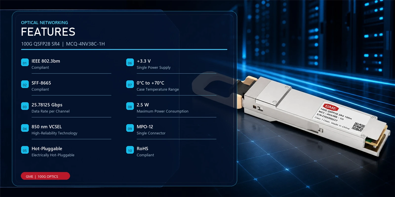
1. Why 10 km Is the Awkward Distance
Among the four mainstream 100G routes, LR4 occupies a peculiar position:
|
Approach |
Fiber |
Multiplexing |
Reach |
Connector |
|
SR4 |
Multimode |
4-lane parallel, 850 nm |
70 / 100 m |
MPO12 |
|
CWDM4 |
Single-mode |
4-wavelength CWDM, 1271–1331 nm |
2 km |
Duplex LC |
|
LR4 |
Single-mode |
4-wavelength LAN-WDM, ~1300 nm |
10 km |
Duplex LC |
|
ER4 |
Single-mode |
4-wavelength LAN-WDM with EML |
40 km |
Duplex LC |
The difficulty at 10 km is not "going far" - it is "going far enough with the cheapest possible components":
• Multimode is out. Modal dispersion has completely smeared a 25G signal by the few-hundred-meter mark.
• Parallel single-mode is out. Four fiber pairs over 10 km quadruples fiber cost, and in metro and campus scenarios fiber is precisely the scarcest resource.
• Coherent is out. A coherent link will happily run hundreds of kilometers, but a 100G coherent module draws 5–10× the power of LR4 and costs more than 3× as much. At 10 km that is pure waste.
Only one path remains: wavelength division on single-mode fiber, with few wavelengths and generous spacing. Four wavelengths, duplex LC, compatibility with installed single-mode cabling - those are LR4's entire design constraints.
2. Why These Four Wavelengths
The datasheet specifies four center wavelengths:
1295.56 nm 1300.05 nm 1304.58 nm 1309.14 nm
Adjacent spacing is approximately 4.49, 4.53, and 4.56 nm, which corresponds to roughly 800 GHz in frequency. The conversion is:
Δf = c · Δλ / λ² ≈ (3×10⁸ × 4.5×10⁻⁹) / (1.3×10⁻⁶)² ≈ 800 GHz
Why 800 GHz, rather than CWDM's 20 nm (about 3.5 THz) or DWDM's 100 GHz? Three engineering trade-offs constrain each other:
First, the window must sit near 1310 nm. The zero-dispersion point of G.652 single-mode fiber lies at about 1310 nm. In the 1300 nm window the chromatic dispersion coefficient is near zero, so 10 km of transmission needs essentially no dispersion compensation. Move to 1550 nm and the coefficient is about 17 ps/(nm·km), accumulating 170 ps/nm over 10 km - which would require compensation for a 25G signal, or a significant dispersion penalty. Attenuation in the 1310 nm window is roughly 0.35–0.40 dB/km, or 3.5–4 dB over 10 km, which still leaves margin inside a 6.3 dB budget.
Second, the spacing cannot be too wide, or the MUX/DeMUX will not fit. A four-channel combiner operating at 20 nm spacing needs more thin-film filter layers and more volume, conflicting with the QSFP28 envelope. At 4.5 nm the combiner can be built from PLC (planar lightwave circuit) or miniaturized TFF and integrated directly inside the module.
Third, the spacing cannot be too narrow, or laser costs become unmanageable. Per-lane wavelength tolerance in the datasheet is roughly ±1.03 nm (Lane 0, for example, is allowed from 1294.53 to 1296.59 nm). That corresponds to about ±190 GHz, which an ordinary uncooled DFB can meet through wavelength binning. Tighten to 100 GHz spacing and you need TEC stabilization or wavelength locking - stepping both power and cost up a level.
800 GHz sits precisely at the balance point of these three: small enough dispersion, small enough components, cheap enough lasers.
3. Inside the Implementation
3.1 Architecture: 4 Transmit, 4 Receive, Built-In Combiner
Internally, LR4 contains a complete wavelength-division system:
TX0 --> DFB (1295.56nm) --+
TX1 --> DFB (1300.05nm) --+--> MUX --> LC duplex (TX)
TX2 --> DFB (1304.58nm) --+
TX3 --> DFB (1309.14nm) --+
RX0 <-- PIN/TIA <--+
RX1 <-- PIN/TIA <--+--> DeMUX <-- LC duplex (RX)
RX2 <-- PIN/TIA <--+
RX3 <-- PIN/TIA <--+
Four transmitters, four receivers, one optical multiplexer, and one demultiplexer, all inside a QSFP28 package. The entire link presents just one LC pair to the outside world - and that is LR4's most fundamental advantage over parallel approaches: it compresses an 8-fiber requirement into 2 fibers.
On a 12-fiber single-mode cable, this means SR4 can light up only one 100G link (using 8 fibers), while LR4 can light up six. Where fiber is scarce, that difference is decisive.
3.2 Transmitter: Four Hard Numbers for DFB
All four transmit lanes use DFB (distributed feedback) lasers. The datasheet imposes four key constraints:
Side-mode suppression ratio, SMSR ≥ 30 dB. If side modes are insufficiently suppressed, they create crosstalk in adjacent channels after combining. 30 dB is the basic threshold for any WDM system.
Relative intensity noise, RIN ≤ −130 dB/Hz. RIN is output power fluctuation, which adds directly to the signal as noise. DFB lasers typically sit around −140 dB/Hz, leaving ample margin against the −130 dB/Hz requirement.
Extinction ratio, ER ≥ 4 dB. Twice as strict as SR4's 2 dB. A DFB has good P-I linearity, so achieving 4 dB or more does not sacrifice modulation speed - which is why the standard sets a higher ER requirement for single-mode.
Transmitter and dispersion penalty, TDP ≤ 2.2 dB. TDP combines eye closure at the transmitter with residual dispersion penalty and is the final measure of transmit quality.
Principal transmitter specifications:
|
Parameter |
Symbol |
Min |
Max |
Unit |
|
Data rate per lane |
- |
25.78125 ± 100 ppm |
- |
Gb/s |
|
Lane 0 wavelength range |
λ0 |
1294.53 |
1296.59 |
nm |
|
Lane 1 wavelength range |
λ1 |
1299.02 |
1301.09 |
nm |
|
Lane 2 wavelength range |
λ2 |
1303.54 |
1305.63 |
nm |
|
Lane 3 wavelength range |
λ3 |
1308.09 |
1310.19 |
nm |
|
Average launch power per lane |
- |
−4.3 |
+4.5 |
dBm |
|
Total average launch power |
- |
- |
10.5 |
dBm |
|
OMA per lane |
- |
−1.3 |
+4.5 |
dBm |
|
Launch power in OMA minus TDP |
- |
−2.3 |
- |
dBm |
|
Extinction ratio |
ER |
4 |
- |
dB |
|
Side-mode suppression ratio |
SMSR |
30 |
- |
dB |
|
Relative intensity noise |
RIN |
- |
−130 |
dB/Hz |
|
Average launch power, TX off state |
- |
- |
−30 |
dBm |
|
Transmitter reflectance |
- |
- |
−12 |
dB |
One easily overlooked detail: "total average launch power ≤ 10.5 dBm." Each lane can reach +4.5 dBm, so in theory the sum could reach +10.5 dBm - meaning this limit specifically prevents all four lanes from running at full power simultaneously. The reason is that the fiber and connectors downstream of the combiner must handle the aggregate power; exceeding it accelerates endface aging and damage.
3.3 Receiver: −8.6 dBm OMA Sensitivity
The key receive-side numbers:
• OMA sensitivity ≤ −8.6 dBm. This is the baseline for deciding whether a link closes, measured with PRBS 2³¹−1 at a bit error rate of 1×10⁻¹².
• Stressed sensitivity ≤ −6.8 dBm. Measured with an additional 1.8 dB vertical eye closure, 0.30 UI of J2 jitter, and 0.47 UI of J9 jitter - much closer to real conditions.
• Average receive power range −10.6 to +4.5 dBm, a dynamic range of 15.1 dB.
• Damage threshold 5.5 dBm, 2 dB higher than SR4's 3.4 dBm, indicating greater overload tolerance in the photodiode.
• Receiver reflectance ≤ −26 dB, far stricter than SR4's −12 dB. The reason is direct: reflections in a single-mode system travel back along the fiber and interfere inside the DFB, degrading RIN. Multimode systems do not exhibit this mechanism.
3.4 Link Budget: The 6.3 dB Line
Line up the transmit and receive numbers and the link budget follows:
P_budget = (−2.3 dBm) − (−8.6 dBm) = 6.3 dB
Note that this uses "launch power in OMA minus TDP" (−2.3 dBm) and "OMA sensitivity" (−8.6 dBm) - two quantities on the same basis. Using average launch power (−4.3 dBm) against average receive sensitivity yields a completely wrong conclusion. This is the most common basis error in link engineering.
How the 6.3 dB is spent over 10 km of single-mode:
|
Item |
Typical |
Worst Case (G.652.D limit) |
|
Fiber loss (10 km) |
3.5 dB (0.35 dB/km) |
4.0 dB (0.40 dB/km) |
|
Two LC connectors |
0.6 dB |
1.0 dB |
|
Splice points (×2) |
0.1 dB |
0.2 dB |
|
Total |
4.2 dB |
5.2 dB |
|
Remaining margin |
2.1 dB |
1.1 dB |
This explains a field observation: two LR4 links at nominally the same 10 km, one runs stably and one errors constantly. The difference is usually not the module but the fiber itself - legacy G.652.A/B fiber can approach 0.5 dB/km at 1310 nm, which is 5 dB over 10 km; add connectors and the margin nearly vanishes. Link design must be calculated against worst-case values, not typical ones.
3.5 Dispersion: Why This Tier Barely Has to Care
G.652 fiber has its zero-dispersion point at 1310 nm, with a zero-dispersion slope of about 0.092 ps/(nm²·km). Within the narrow 1295–1310 nm window, the dispersion coefficient stays within roughly ±0.5 ps/(nm·km).
For a 25.78 Gb/s NRZ signal, one UI is about 38.8 ps. Even on a worst-case estimate, the dispersion accumulated over 10 km is under 5 ps/nm, while DFB spectral width is typically below 0.1 nm - a total dispersion penalty of less than 1 ps, entirely negligible.
This is precisely the engineering watershed between LR4 and 1550 nm approaches (ER4, ZR4): the 1300 nm window trades "zero dispersion" for "no compensation required," eliminating both EML lasers and dispersion-compensating components. The price is higher attenuation than at 1550 nm (0.35 vs 0.20 dB/km), but over 10 km that costs only about 1.5 dB - far less than the component cost saved.
3.6 Electrical and Power
High-speed side: CAUI-4, four 25.78125 GBd differential lanes, per 802.3bm.
Low-speed side: SFF-8679, with I2C digital diagnostics (DDM) per SFF-8636.
38-pin card edge: identical QSFP28 definition to SR4, so the same switch port can accept either module.
Supply 3.14–3.46 V, nominal 3.3 V.
Power < 4 W; low-power mode (LPMode) < 1.5 W.
Operating case temperature 0 to +70 °C; storage −40 to +85 °C.
The power figure is worth comparing: LR4's 4 W is 1.6× SR4's 2.5 W. The extra 1.5 W goes mainly to the bias circuitry of four DFBs, compensation for combiner insertion loss, and higher TIA gain on the receive side. On a 32-port 100G line card that 1.5 W becomes 48 W of chassis power - in a high-density room, that is often more worth calculating than the unit price.
4. Typical Applications
4.1 Campus and Metro 10 km Links
This is LR4's standard scenario. Inter-building links within a campus, or between two equipment rooms in the same city, are typically 2–10 km and already have single-mode cable in place. The duplex LC interface mates directly with existing ODFs and patch cords, minimizing retrofit work.
4.2 5G Midhaul and Backhaul
With CU/DU separation in 5G, midhaul spans commonly run from a few kilometers to the low teens. LR4 provides 100G of midhaul capacity over a single fiber pair, putting the least strain on the operator's fiber resources.
4.3 Short-Haul Data Center Interconnect
For metro DCI within 10 km, LR4 is the most economical 100G option. Beyond 10 km the design must move to ER4 or coherent.
4.4 Enterprise Backbone and Storage
Core-to-aggregation links in large enterprises and cross-building SAN links also commonly use LR4. Its multi-vendor interoperability, grounded in 802.3ba, matters more here than raw performance.
5. SR4 vs LR4: The Choice in One Table
|
Dimension |
SR4 |
LR4 |
|
Fiber type |
Multimode OM3/OM4 |
Single-mode G.652 |
|
Operating wavelength |
850 nm |
1295–1310 nm |
|
Multiplexing |
4-lane spatial parallel |
4-wavelength LAN-WDM |
|
Fiber count |
8 (MPO12) |
2 (duplex LC) |
|
Reach |
70 m (OM3) / 100 m (OM4) |
10 km |
|
Laser |
VCSEL |
DFB |
|
Link budget |
1.9 dB |
6.3 dB |
|
Extinction ratio requirement |
≥ 2 dB |
≥ 4 dB |
|
Power |
2.5 W |
< 4 W |
|
FEC required |
Mandatory |
Recommended (can be disabled) |
|
Main cost driver |
Multimode fiber and MPO cabling |
Single-mode fiber and DFB devices |
The selection logic is really one sentence: check which distance tier you fall into, and whether fiber is scarce.
Under 100 m, high density inside the rack → SR4.
Around 500 m, cross-room → PSM4.
Around 2 km, fiber-constrained → CWDM4.
Around 10 km, existing single-mode → LR4.
6. Deployment Notes
1. Calculate the link budget on worst-case values. Use 0.40 dB/km (the G.652.D limit) rather than 0.35 dB/km, and connector limits rather than typicals. The difference between 1.1 dB and 2.1 dB of margin decides whether a link is "maintenance-free for three years" or "one bit-error report per quarter."
2. Do not mix bases. Use "launch power in OMA minus TDP" on the transmit side and "OMA sensitivity" on the receive side - same basis at both ends. Mixing average power in produces a conclusion that is more than 2 dB too optimistic.
3. Pair modules, prefer the same batch. Standards-based interoperability works, but vendors differ in TDP headroom and wavelength binning strategy; mixed pairing leaves less real margin than theory suggests.
4. Endface cleaning is not optional. With a 9 µm single-mode core, a single dust particle can block the path entirely. LC endface inspection belongs in routine maintenance.
5. Watch four-lane balance in DDM. The four wavelengths see slightly different insertion loss in the combiner. Under normal conditions the receive-power spread across lanes should stay within 1.5 dB. A persistently low lane usually indicates combiner degradation or an aging laser on that lane.
6. Case temperature is not ambient temperature. The 0 to +70 °C rating refers to case temperature. On high-density line cards, module cases typically run 15–20 °C above inlet air. Design against measured case temperature, not room temperature.
7. Mind the total launch power. With all four lanes at full power the total approaches the 10.5 dBm limit. During long-duration burn-in at full power, confirm the far end can tolerate it.
7. Conclusion
What is elegant about LR4 is how restrained its parameter set is.
An 800 GHz spacing - eight times wider than DWDM, four times narrower than CWDM - is exactly enough to keep uncooled DFBs viable, fit the combiner inside QSFP28, and make the dispersion penalty negligible. A 6.3 dB budget - not large, but just enough margin over 10 km of G.652. Four watts - not low, but an order of magnitude below coherent.
There is almost nothing "state of the art" in this product: no EML, no TEC, no coherent DSP, no signal processing beyond forward error correction. It simply combines four ordinary DFBs, one combiner, and one demultiplexer in the most economical way over two fibers.
And that restraint is exactly why it has become the most universal 100G interface in the 10 km tier over the past decade - when a technology is just barely sufficient in every dimension, it is usually the final answer.


