

1. The Shift to Native 100G/Lane in 400G Networks
As data center switching ASICs, server NICs (such as ConnectX-7), and AI compute clusters transition to native 100G/112G PAM4 SerDes architectures, legacy 8-lane 400G form factors (which rely on 8×50G electrical interfaces and internal gearboxes) introduce unnecessary power overhead and board complexity. The 400G QSFP112 DR4 optical transceiver addresses this evolution by matching a 4-lane 100G PAM4 electrical interface directly to 4 parallel 100G optical lanes in a compact, hot-pluggable QSFP footprint. This 1:1 lane mapping eliminates gearbox latency, reduces module power consumption to ≤ 10 W, and maximizes faceplate density for 400G switches and GPU servers.

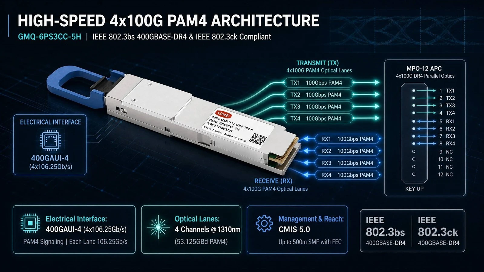
2. Inside the 400GBASE-DR4 High-Speed Architecture
Engineered in compliance with QSFP112 MSA Rev 2.0, IEEE 802.3bs (400GBASE-DR4), and IEEE 802.3ck (400GAUI-4) standards, the GME GMQ-6PS3CC-5H converts four channels of 100G PAM4 electrical signals into four parallel single-mode optical signals for an aggregate throughput of 400 Gbps.
Electrical Host Side (400GAUI-4): Supports 4 channels of PAM4 electrical signaling at 106.25 Gbps per lane (53.125 GBd), connecting seamlessly to modern 112G-per-lane switch ASICs and network adapters without retimer/gearbox conversions.
Parallel Optical Engine (4×100G PAM4): Operates in the O-band around a 1310 nm center wavelength (1304.5 nm to 1317.5 nm range). Each optical lane transmits at 53.125 GBd PAM4 with an average launch power of -2.9 to +4.0 dBm, Outer Optical Modulation Amplitude ($\text{OMA}_{\text{outer}}$) of -0.8 to +4.2 dBm, and a tight Transmitter and Dispersion Eye Closure for PAM4 (TDECQ) of ≤ 3.4 dB to ensure high signal integrity.
Optical Interface & Reach: Equipped with a single MPO-12/MTP-12 APC (8° angled) receptacle utilizing 8 active fibers (4 TX and 4 RX). With host Forward Error Correction (FEC) enabled, it achieves up to 500 m (0.5 km) transmission over Single-Mode Fiber (SMF), delivering a post-FEC Bit Error Rate (BER) down to 1×10−121 \times 10^{-12}1×10⁻¹² (pre-FEC BER of $2.4 \times 10^{-4}$).
Thermal Efficiency & Management: Packaged in a QSFP112 Type 2 (87.4 mm) housing, the module runs on a single +3.3 V supply with a maximum power dissipation of 10 W across a 0°C to +70°C commercial operating temperature range, managed via CMIS 5.0 with real-time Digital Diagnostic Monitoring (DDM).
3. Core Technical Specifications (Reference: GME GMQ-6PS3CC-5H)
| Parameter | Specification |
|---|---|
| Part Number | GMQ-6PS3CC-5H |
| Form Factor | QSFP112 Type 2 (87.4 mm, Hot-Pluggable) |
| Aggregate Data Rate | 400 Gbps (4 × 100G PAM4 Channels) |
| Electrical Interface | 400GAUI-4 (4 × 106.25 Gbps PAM4, IEEE 802.3ck) |
| Signaling Rate per Lane | 53.125 GBd (PAM4) |
| Optical Wavelength | 1310 nm Typical (1304.5 nm – 1317.5 nm) |
| Fiber Type & Max Reach | Single-Mode Fiber (SMF), up to 500 m (0.5 km) with Host FEC |
| Optical Connector | Single MPO-12 / MTP-12 APC (8° Angled) Receptacle |
| Transmitter Optical Specs | Avg Power: -2.9 to +4.0 dBm; OMAouter\text{OMA}_{\text{outer}}OMAouter: -0.8 to +4.2 dBm; ER ≥ 3.5 dB; TDECQ ≤ 3.4 dB; SMSR ≥ 30 dB |
| BER Performance | Pre-FEC BER: 2.4×10−42.4 \times 10^{-4}2.4×10⁻⁴ | Post-FEC BER: 1×10−121 \times 10^{-12}1×10⁻¹² |
| Max Power Consumption | ≤ 10 W (+3.3 V Single Power Supply) |
| Operating Case Temperature | 0°C to +70°C |
| Management Interface | CMIS 5.0 with Real-Time DDM |
| Standards & Compliance | QSFP112 MSA Rev 2.0, IEEE 802.3bs 400GBASE-DR4, RoHS 2.0, EN 60825-1 Class 1 Laser |
4. Key Application Scenarios
A. 400G Ethernet Spine-Leaf & ToR Switching
In modern cloud data centers, the GMQ-6PS3CC-5H provides high-density 400G uplinks between Top-of-Rack (ToR) switches and Leaf-Spine aggregation layers. Furthermore, its 4-channel parallel DR4 architecture supports 1×400G to 4×100G DR1 breakout topologies using an MPO-12 to 4×Duplex LC harness cable, allowing a single 400G switch port to connect directly to four independent 100G server NICs or switches.
B. AI Clusters & NDR 400G InfiniBand Interconnects
Large-scale GPU compute pods require ultra-low latency and lossless transmission across east-west fabrics. Operating at native 4×100G PAM4 without internal gearbox conversion delay, the 400G QSFP112 DR4 module serves as an ideal optical interconnect between 400G server network adapters and NDR 400G InfiniBand or RoCEv2 switches over distances up to 500 meters, including 2:1 splitter connections from 800G 2xDR4 switch ports.
C. Hyperscale Data Center Interconnect (DCI) & Enterprise Core Routing
For multi-hall data centers and cloud campus networks, 500-meter single-mode reach bridges distributed server rooms and core aggregation routers without the high cost of WDM or coherent transceivers. Built-in CMIS 5.0 DDM allows network operators to monitor per-lane optical power, temperature, and voltage in real time for proactive fault isolation.
5. Deployment Best Practices for Network Engineers
Use APC (8°) Single-Mode MPO-12 Cabling: The DR4 optical port requires an MPO-12 APC (8° angled polish) single-mode patch cord (typically Type B polarity for transceiver-to-transceiver links) to minimize optical return loss (Transmitter Reflectance ≤ -26 dB). Never plug flat UPC connectors into an APC receptacle.
Enable Host FEC: To achieve the full 500 m reach over SMF with a post-FEC BER of 1×10−121 \times 10^{-12}1×10⁻¹², ensure KP4 Forward Error Correction (RS-FEC) is enabled on the host switch or NIC port.
Verify QSFP112 Port Compatibility: While QSFP112 shares a similar physical width with legacy QSFP28/QSFP56 cages, verify that your host switch or NIC port specifically supports QSFP112 / 400GAUI-4 (106.25 Gbps per electrical lane) and CMIS 5.0 management.


