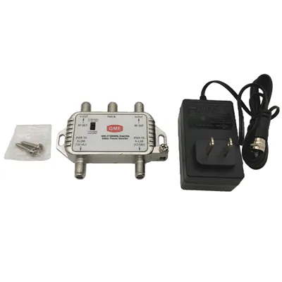
In the realm of high - frequency electronics, couplers play a crucial role. As a seasoned coupler supplier, I've witnessed firsthand the significance of these devices in various high - frequency applications. In this blog, I'll delve into how a coupler works in a high - frequency band, exploring its principles, applications, and the different types available.
Principles of Coupling in High - Frequency Bands
At its core, a coupler is a passive device that is used to sample a portion of the power from a transmission line. In high - frequency bands, typically ranging from several hundred megahertz to several gigahertz, the physical behavior of electromagnetic waves and the properties of materials become even more critical.
The basic principle of coupling in high - frequency bands is based on the interaction of electromagnetic fields. When an electromagnetic wave travels through a transmission line, it creates a magnetic field around the conductor. A coupler is designed to pick up a fraction of this magnetic field and transfer it to another transmission line or port.
One of the key concepts in understanding how a coupler works is the coupling coefficient. The coupling coefficient (C) is defined as the ratio of the power at the coupled port (Pc) to the power at the input port (Pi), expressed in decibels (dB):
[C = 10\log_{10}\left(\frac{P_c}{P_i}\right)]
For example, a coupler with a coupling coefficient of 20 dB means that 1% of the input power is coupled to the coupled port.
Another important parameter is the directivity (D) of the coupler. Directivity measures the ability of the coupler to isolate the forward - traveling wave from the backward - traveling wave. A high directivity indicates that the coupler can accurately sample the forward - traveling power while minimizing the influence of the reflected power.
Types of Couplers in High - Frequency Bands
There are several types of couplers commonly used in high - frequency bands, each with its own unique characteristics and applications.
Directional Couplers
Directional couplers are perhaps the most widely used type of coupler in high - frequency systems. They are designed to couple power from one transmission line to another in a specific direction. A typical directional coupler has four ports: an input port, an output port, a coupled port, and an isolated port.
The operation of a directional coupler is based on the principle of traveling waves. When a signal enters the input port, most of the power travels to the output port. A small fraction of the power is coupled to the coupled port, while the isolated port is designed to have minimal power transfer. Directional couplers are used in applications such as power monitoring, signal sampling, and antenna feed systems. You can learn more about our CATV Directional Coupler.
Hybrid Couplers
Hybrid couplers are another important type of coupler in high - frequency applications. They are used to split or combine signals with specific phase relationships. A common type of hybrid coupler is the 3 - dB hybrid coupler, which splits the input power equally between two output ports with a 90 - degree phase difference.
Hybrid couplers are widely used in RF and microwave circuits, such as mixers, amplifiers, and antenna arrays. They are also used in communication systems for diversity reception and power combining.
Branch - Line Couplers
Branch - line couplers are a type of planar coupler that consists of a series of transmission line segments connected in a specific pattern. They are typically used in microstrip or stripline circuits in high - frequency applications.
Branch - line couplers are known for their compact size and good performance over a relatively wide bandwidth. They are commonly used in RF and microwave integrated circuits, such as filters, oscillators, and impedance matching networks.
Applications of Couplers in High - Frequency Bands
Couplers have a wide range of applications in high - frequency bands, across various industries.
Telecommunications
In telecommunications, couplers are used in base stations, mobile phones, and satellite communication systems. They are used for power monitoring, signal sampling, and power splitting. For example, in a base station, a directional coupler can be used to monitor the power output of the transmitter, ensuring that it operates within the specified limits.
Radar Systems
Radar systems rely on couplers for signal processing and power distribution. Directional couplers are used to sample the transmitted and received signals, allowing for accurate measurement of the radar's performance. Hybrid couplers are also used in radar systems for phase - shifting and power combining.
Test and Measurement
In test and measurement applications, couplers are used to sample high - frequency signals for analysis. They are used in spectrum analyzers, network analyzers, and other test equipment to measure the power, frequency, and phase of the signals.
Design Considerations for High - Frequency Couplers
Designing a high - frequency coupler requires careful consideration of several factors.
Material Selection
The choice of materials is crucial in high - frequency coupler design. The dielectric material used in the transmission lines can have a significant impact on the coupler's performance. Materials with low loss and stable dielectric constant are preferred to minimize signal attenuation and ensure accurate coupling.
Physical Dimensions
The physical dimensions of the coupler, such as the length and width of the transmission lines, also play an important role. In high - frequency bands, the wavelength of the electromagnetic waves is relatively short, so the dimensions of the coupler need to be carefully optimized to achieve the desired coupling coefficient and directivity.
Manufacturing Tolerances
Manufacturing tolerances can affect the performance of high - frequency couplers. Small variations in the dimensions or material properties can lead to changes in the coupling coefficient and directivity. Therefore, tight manufacturing tolerances are required to ensure consistent performance.
Our High - Frequency Coupler Offerings
As a coupler supplier, we offer a wide range of high - frequency couplers to meet the diverse needs of our customers. Our 1 GHz CATV Trunk Link Directional Coupler is designed for use in CATV systems, providing reliable coupling and high directivity at the 1 GHz frequency band.
We also offer custom - designed couplers to meet specific customer requirements. Our team of experienced engineers can work closely with you to design and manufacture couplers that are optimized for your application.
Conclusion
In conclusion, couplers are essential components in high - frequency systems. Understanding how they work, the different types available, and their applications is crucial for anyone involved in high - frequency electronics. Whether you're in the telecommunications, radar, or test and measurement industry, a well - designed coupler can significantly improve the performance of your system.
If you're interested in learning more about our coupler products or have specific requirements for your application, we invite you to contact us for a procurement discussion. Our team is ready to assist you in finding the best coupler solutions for your needs.


References
- Pozar, D. M. (2011). Microwave Engineering (4th ed.). Wiley.
- Collin, R. E. (2001). Foundations for Microwave Engineering (2nd ed.). McGraw - Hill.
- Matthaei, G. L., Young, L., & Jones, E. M. T. (1964). Microwave Filters, Impedance - Matching Networks, and Coupling Structures. McGraw - Hill.