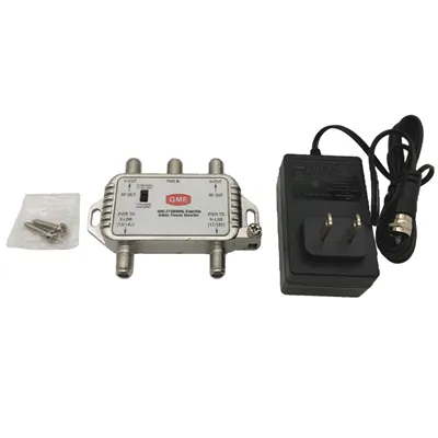
As a supplier of demultiplexers, ensuring the proper functionality of these devices is crucial. Demultiplexers play a vital role in various fields, especially in communication and signal processing systems. In this blog, I'll share some effective methods on how to test the functionality of a demultiplexer.
Understanding the Basics of a Demultiplexer
Before diving into the testing procedures, it's essential to have a clear understanding of what a demultiplexer is. A demultiplexer is a device that takes a single input signal and routes it to one of several output lines based on the select signals. For instance, in a 1-to-4 demultiplexer, there is one input line, two select lines (since 2² = 4), and four output lines.
Pre - testing Preparations
1. Power Supply Check
First and foremost, ensure that the power supply to the demultiplexer is stable and within the specified voltage range. Fluctuations in the power supply can lead to inaccurate test results. Use a reliable power source and a multimeter to measure the voltage across the power pins of the demultiplexer.
2. Signal Source Preparation
Prepare a suitable signal source. This could be a function generator that can produce various types of signals such as sine waves, square waves, or pulses. The frequency and amplitude of the signal should be set according to the specifications of the demultiplexer.
3. Oscilloscope Setup
An oscilloscope is an indispensable tool for testing a demultiplexer. Connect the oscilloscope probes to the input and output lines of the demultiplexer. Set the appropriate timebase and voltage scale on the oscilloscope to clearly view the signals.
Testing the Select Lines
1. Logic Level Testing
The select lines of a demultiplexer determine which output line the input signal will be routed to. Use a logic analyzer or a multimeter to check the logic levels of the select lines. For a binary - based demultiplexer, the select lines should be able to represent all possible binary combinations.
For example, in a 1 - to - 4 demultiplexer with two select lines (S0 and S1), the possible combinations are 00, 01, 10, and 11. Apply each combination of logic levels to the select lines using a logic source and observe the corresponding output on the oscilloscope.
2. Select Line Sensitivity
Test the sensitivity of the select lines. Slightly vary the voltage levels around the nominal logic levels (e.g., for TTL logic, 0V for logic 0 and 5V for logic 1) and check if the demultiplexer still functions correctly. This helps to ensure that the demultiplexer can tolerate small variations in the select line signals.


Testing the Input and Output Signals
1. Signal Integrity at the Input
Send a known signal from the signal source to the input of the demultiplexer. Check the signal integrity at the input using the oscilloscope. Look for any distortion, noise, or attenuation of the signal. If the input signal is not clean, it can affect the performance of the demultiplexer.
2. Output Signal Verification
For each combination of select line inputs, check the output signals on the corresponding output lines. The output signal should be a replica of the input signal with minimal distortion. Measure the amplitude, frequency, and phase of the output signal and compare them with the input signal.
If the demultiplexer is working correctly, when the select lines are set to a particular combination, the input signal should appear only on the corresponding output line, and the other output lines should have no significant signal.
3. Crosstalk Testing
Crosstalk is an important parameter to test. Crosstalk occurs when a signal on one output line interferes with the signals on other output lines. To test for crosstalk, send a signal to the input and set the select lines to a specific combination. Then, measure the signal levels on the non - selected output lines. The signal levels on these non - selected lines should be well below the specified crosstalk limit.
Testing for Fault Conditions
1. Overvoltage and Undervoltage Testing
Apply overvoltage and undervoltage conditions to the power supply of the demultiplexer within the limits that the device can tolerate. Observe the behavior of the demultiplexer. It should either shut down gracefully or maintain some level of functionality without permanent damage.
2. Signal Overload Testing
Send a signal with an amplitude higher than the specified input range to the demultiplexer. Check if the device can handle the overload without malfunctioning or getting damaged.
Special Considerations for DBS Demultiplexer
If you are dealing with a DBS Demultiplexer, there are some additional testing steps. DBS demultiplexers are often used in satellite communication systems.
1. Frequency Response Testing
DBS signals operate at specific frequencies. Test the frequency response of the DBS demultiplexer by sending signals at different frequencies within the operating range. Check if the demultiplexer can correctly route the signals at all these frequencies.
2. Polarization Testing
Satellite signals can have different polarizations (e.g., vertical and horizontal). Test the DBS demultiplexer's ability to handle different polarizations. Send signals with different polarizations to the input and check if the demultiplexer can route them correctly to the appropriate output lines.
Documentation and Reporting
After completing all the tests, document the test results thoroughly. Include details such as the input signals used, the select line combinations, the output signal measurements, and any observed faults or issues. Generate a comprehensive test report that can be used for quality control and customer support.
Conclusion
Testing the functionality of a demultiplexer is a multi - step process that requires careful attention to detail. By following the methods described above, you can ensure that your demultiplexers meet the highest quality standards. As a demultiplexer supplier, we are committed to providing products that are thoroughly tested and reliable.
If you are interested in purchasing high - quality demultiplexers or have any questions about our testing procedures, we welcome you to contact us for further discussions and potential procurement opportunities.
References
- "Digital Logic and Computer Design" by M. Morris Mano.
- "Communication Systems" by Simon Haykin.